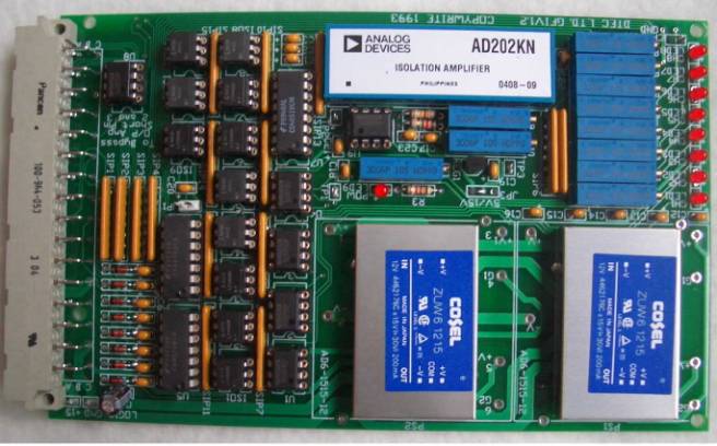
GFIV1.2 Ground Fault Monitor Circuit Board
- 8 Separate Channels from 5 to 600VDC, or 24 to 3000VAC.
- 1 Switched Analog Channel.
Able to read any of the 8 Ground fault channels
- Electrical:
- 15VDC input at 230mA
- Ground Fault Monitor 26.5VDC high impedance >3M Ohm
- Analog Channel selected BCD 3 wire, 0-15VDC
- Analog Output 0-5VDC 25mA max.
- Digital Output 8 channels, 0-5VDC or 0-15VDC. Normal or inverted
outputs.
- LED indicator and digital output are “ON” after less than 500KOhms
sensed.
- Mechanical:
- Single Height (1U) board size
- Less than ½ inch thickness.
- Optical isolation between sensed circuits and power supply.
- See GFITERM Ground
Fault Term Card associated
products.
- Higher Voltages > 120VAC
require sense blocks
- Stock item, US$850.00 each
Download
Circuit Description
The DTEC Ltd. GFIV1.2 ground fault monitoring board
places a high impedance (~2M2 ohms) voltage source of +25.6 VDC, with respect
to chassis ground, onto eight channels. It then measures the drop across
sensing resistors. These (1M2 single phase 1M8 3 phase) sensing resistors are
found either installed on the GFIV1.2 termination board or installed in an
epoxy block close to the high voltage source. If a ground fault condition is
developing this +25.6 vdc level decreases. If +25.6 VDC is measured with
respect to chassis ground on the monitored channel there is no ground fault. As
the this voltage drops, a corresponding decrease in the ground fault resistance
level is sensed and an increasing analog output voltage for that channel is
produced. If the ground fault level becomes less than an equivalent of 500K
ohms to ground the digital alarm is raised on the board.
There are 5 sections to the circuit board:
- Power Supply
The 2 - DC-DC converters receive a logic +15 vdc and output +/- 15 vdc. These work in series to create a +60 vdc circuit and a single +15 vdc with respect to chassis ground. Minimum current required by the board is 2 amps to startup and nominally 500ma running. Typical load in a no ground fault condition is 170mA (normal operation). - Voltage Comparitor
This section compares the trip level (set by Pot 11 and measured on test point 1) to the measured sense input level. Pot 11 is set to 6.00 VDC or 500 KOhms. - Digital Output
This section triggers the digital output to be enabled. This level is either active high (+5 or +12 vdc) or active low (0 vdc). The active high/low is selectable by Jumper 1 (JP1). No matter what the state of JP1 the LEDs on the board only illuminate if the ground fault trip level is reached. - Analog Output/Isolator
This section outputs 1 voltage as selected by the bit select inputs. ( C12, C14, and A14). The output is with reference to power supply ground and should range from +0.00 to +5.00 vdc. - Bit Select Input
This is the section which selects the channel that will be routed through the analog isolator. The following is a table for the bit select levels and the corresponding channel to be routed to the analog output.
|
Note:lsb : Least Significant Bit
msb : Most Significant Bit
0 : Logic Ground
1 : Logic +15 vdc
Board Setup
The ground fault board is set up at the
factory to measure ground faults ranging from
No foreign wiring (system interconnections to sense
lines) should be connected to the board only the essential wiring.
Connections for the board
Terminal
Decription
Edge Term
board
C2 39
Chassis Ground
C4 38 Logic
Ground
C10 1 Logic
+12 vdc
C12 2 Bit
Select 1 (lsb)
C14 3 Bit
Select 2
A14 4 Bit
Select 3 (msb)
C16 5
Digital Output Alarm For Channel 1
C18 6
Digital Output Alarm For Channel 2
C20 7
Digital Output Alarm For Channel 3
C22 8
Digital Output Alarm For Channel 4
A16 9
Digital Output Alarm For Channel 5
A18 10
Digital Output Alarm For Channel 6
A20 11
Digital Output Alarm For Channel 7
A22 12
Digital Output Alarm For Channel 8
C26 36
Channel 1 Input Sense Lines
35
C28 34
Channel 2 Input Sense Lines
33
C30 32
Channel 3 Input Sense Lines
31
C32 30
Channel 4 Input Sense Lines
29
A26 28
Channel 5 Input Sense Lines
27
A28 26
Channel 6 Input Sense Lines
25
A30 24
Channel 7 Input Sense Lines
23
A32 22
Channel 8 Input Sense Lines
21
Test points used on the board
Input logic
voltage level point and ground point found in the rear left corner.
Chassis
ground point found near LED 8
TP1 found
near power LED9 and C18
TP3 found
near C19 and P10
Setup
Tune Pot 11 (P11) so the voltage at Test
Point 1 (TP1) is +6.00 vdc with respect to chassis ground. This calibrates the
digital output trip level to activate at ~500K ohms. Tune Pots 1 through 8 (P1
to P8) so the voltage at the junction of the diode and capacitor is +10.00 vdc
with respect to chassis ground. For example to set up channel 1: - place the
“+” ve probe of multi-meter on the junction of D1 (diode 1) and C1 (capacitor
1) and the “-“ ve on the chassis ground. - tune P1 until the multi-meter reads
+10.00 vdc. E.g. To setup channel 4: Remove U8. U8 cannot output a negative
voltage which is required on setup of the board. U8 will be replaced later.
Place a full ground fault (two 1M2 resistors in series from chassis ground and
the input) on channel #1 (C26). If using the terminal board connect chassis
ground to both terminal #36 and terminal #35. Tune Pot 10 so that the analog
output at pin 3 of U8 is 5.00 VDC. Remove the ground fault on C26 and tune Pot
9 so that the voltage out is -0.83VDC. Replace the ground fault on C26 and
re-tune Pot 10 continuing to go between the no ground fault condition and
ground fault condition tuning Pot 9 and Pot 10 respectively.
** Note **
If you are using the DTEC GFM-3 termination board you
must tie the 2 input sense together ( 35,36 - 33,34 etc.) so the sense
resistors are parallel. If they are already connected to a power supply or a
transformer they don’t need to be tied together but you should be wary of
trying to setup the board in circuit as ground faults even of a small magnitude
will throw off the setup values.
Selectable features:
Jumper 1 JP1 - This selects the digital output from
either active high or active low.
Jumper installed is active low. Jumper removed is
active high. Jumper 3 JP3 - +5 vdc or +15 vdc - This is a hard wire jumper
found in front of P11.